
Introduction
In the modern chemical manufacturing sector, thermal processing stands as one of the most vital unit operations. Consequently, choosing the correct drying technology is paramount for industrial producers operating in the field of water-treatment chemicals, functional inorganic additives, and specialty precipitation products. Indeed, materials such as specialized inorganic coagulants, high-structure precipitated silicas, synthetic silicates, active adsorbents, and inorganic flocculants demand extreme precision during their final thermal dehydration stages. Therefore, evaluating industrial equipment design becomes a top operational priority for plant managers, process engineers, and technical directors worldwide.
Furthermore, thermal drying is far more than a simple moisture-evaporation step. On the contrary, the specific thermal history, mass transfer rate, mechanical agitation, and residence time experienced by a chemical material directly govern its ultimate physical and functional properties. For example, in the production of functional additives, improper drying conditions can permanently damage delicate porous networks, collapse particle structures, reduce active surface areas, or cause unwanted thermal decomposition. Similarly, in the production of coagulant salts used for municipal and industrial water purification, excessive heat can cause loss of chemical activity and severely reduce cold-water dissolution rates. As a result, selecting an appropriately engineered industrial drying system is critical to maintaining strict product performance standards while simultaneously optimizing overall energy consumption.
Company Overview
At GENEX Tech Industries LLP, we engineer and manufacture advanced thermal drying solutions built specifically to handle the challenging physical and chemical properties of inorganic substances. Whether handling pumpable liquid suspensions, thixotropic filter press cakes, delicate extruded hydrogels, fragile crystalline granules, or heavy bulk mineral sludges, matching the material state to the optimal drying dynamic is crucial. Furthermore, because different chemical formulations exhibit distinct moisture binding mechanisms—ranging from free surface moisture to capillary-bound water and hydrated structural water—a one-size-fits-all approach to industrial drying is inherently flawed.
In this comprehensive technical guide, we will thoroughly analyze five essential industrial drying technologies that form the backbone of modern inorganic chemical and water-treatment processing facilities:
- Industrial Spray Drying Systems
- Pneumatic Flash Drying Systems
- Vibratory Fluidised Bed Drying Systems (VFBD)
- Combination Drying Systems (Staged Tray and Fluidised Bed Units)
- Industrial Rotary Drum Drying Systems
In addition, this guide provides extensive operational data, temperature profiles, airflow velocities, residence times, throughput capacities, and detailed comparative matrices. Consequently, process engineering teams can utilize this exhaustive analysis to evaluate thermal equipment options, optimize production lines, and select the best engineered drying solutions for their specific chemical applications.
The Chemical Processing Landscape: Material Characteristics and Challenges
First and foremost, understanding the physical chemistry and structural dynamics of water-treatment and specialty inorganic chemicals is essential prior to selecting thermal processing equipment. Unlike organic products, which often face strict biological degradation limits, inorganic chemicals present a unique set of severe mechanical, thermal, and chemical processing challenges.
1. Inorganic Coagulants and Flocculants
To begin with, inorganic coagulants—including polyaluminum chloride formulations, aluminum sulfate salts, ferric chloride mixtures, ferric sulfate compounds, and polyferric sulfate complexes—serve as foundational chemical agents in municipal water purification and industrial wastewater treatment. In terms of processing, these materials are typically synthesized as concentrated aqueous solutions or wet crystalline slurries.
However, dehydrating these compounds into dry, free-flowing, rapidly soluble powders is notoriously difficult. For instance, these chemical salts are highly hygroscopic, meaning they readily absorb ambient atmospheric moisture if not dried to precise residual levels. Furthermore, many coagulants are exceptionally heat-sensitive. If exposed to excessively high temperatures during the final stages of drying, they undergo thermal dehydroxylation or decomposition into insoluble oxides, thereby losing their primary coagulation efficacy. Additionally, in their wet or semi-moist states, acidic coagulant compounds exhibit extreme corrosiveness toward standard structural metals. Consequently, drying equipment must be manufactured using specialized corrosion-resistant alloys, such as Stainless Steel 316L, Hastelloy C-276, Alloy 20, or Titanium Grade 2.
2. Precipitated Silicas and Synthetic Silicate Additives
On the other hand, precipitated silicas—which extend far beyond general amorphous silica powders into specialized matting agents, rubber reinforcing fillers, high-structure tire silicas, and carrier additives—present entirely different drying challenges. During synthesis, precipitated silica is produced via the controlled acidization of soluble silicate solutions, yielding a wet slurry containing highly branched, porous particle networks.
Even after undergoing intensive mechanical dewatering using membrane filter presses or vacuum drum filters, the resulting filter cake typically retains an extraordinarily high moisture content, often ranging between 70% and 85% water by weight. Furthermore, this wet filter cake is thixotropic and highly cohesive, behaving as a solid paste when stationary but fluidizing under shear stress. Most importantly, the primary functional value of precipitated silica lies in its high specific surface area, large pore volume, and superior oil absorption capacity. Therefore, if the drying system applies excessive mechanical compaction or permits slow, stagnant evaporation, the delicate surface pores collapse due to capillary forces. As a direct result, the final product suffers a irreversible loss of surface area and functional performance.
3. Functional Inorganic Additives and Specialty Adsorbents
Similarly, functional inorganic additives—such as synthetic zeolites, molecular sieve precursors, synthetic calcium silicates, active alumina spheres, titanium-based intermediates, and magnesium hydroxide flame retardants—require strict drying control. These materials are heavily relied upon as functional fillers, catalyst supports, gas-drying agents, and water-softening media.
In these advanced applications, achieving an exact residual moisture content—frequently targeted below 0.5% or even 0.1% by weight—is vital. Furthermore, particle size distribution must be strictly maintained without generating excessive fine dust through particle-to-particle attrition. Consequently, selecting a dryer that offers precise temperature control, adjustable residence time, and gentle mechanical handling is crucial for preserving particle strength, porosity, and catalytic activity.
Deep-Dive Analysis of the Five Core Drying Technologies
To establish a clear technical foundation, the following sections offer an exhaustive, deep-dive examination of each of the five primary industrial dryer types. Every technology is thoroughly detailed regarding its fundamental working principles, mechanical architecture, operational performance parameters, thermal parameters, and specific material suitabilities.
1. Industrial Spray Drying Systems
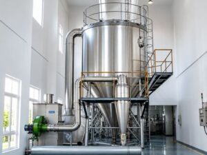
Industrial Spray Drying Process Flow and Mechanics
Operational Parameters and Thermal Data
- Inlet Hot Air Temperature Range: 180°C to 550°C (calibrated to material thermal stability).
- Outlet Exhaust Air Temperature Range: 80°C to 120°C.
- Feed Solids Concentration: 15% to 60% total dissolved or suspended solids.
- Inlet Liquid Moisture Content: 40% to 85% water content.
- Final Product Residual Moisture: 0.5% to 3.0% by weight.
- Droplet Atomization Diameter: 10 microns to 150 microns.
- Residence Time: 5 seconds to 30 seconds (ultra-rapid thermal exposure).
- Evaporation Capacity: 50 kg/h up to 25,000 kg/h of water removal per single unit.
- Thermal Efficiency: 55% to 75% (further enhanced when combined with exhaust air heat recovery loops).
Ideal Product Application: Liquid Coagulants and Precipitated Silica Slurries
Undoubtedly, Industrial Spray Dryers stand as the absolute top-tier drying technology for processing liquid Polyaluminum Chloride solutions, dissolved inorganic salts, and liquid-phase precipitated silica slurries.
Detailed Process Breakdown for Polyaluminum Chloride
- Liquid Feed Preparation: Initially, liquid polyaluminum chloride containing an aluminum oxide concentration between 10% and 18% is pumped continuously into the drying tower.
- High-Speed Rotary Atomization: Next, the liquid feed encounters a rotary atomizer spinning at 18,000 RPM, which immediately splits the fluid into an exceptionally fine, uniform droplet mist.
- Co-Current Thermal Evaporation: Subsequently, hot air entering at 280°C to 350°C contacts the droplet cloud in a co-current flow pattern. Water vaporizes in less than 10 seconds.
- Basicity Preservation: Because evaporation occurs so rapidly, the product temperature stays low, thereby preserving basicity levels between 50% and 85% without breaking chemical bonds.
- Final High-Solubility Powder: Ultimately, the resulting fine, yellow or pale-white powder exhibits an elevated aluminum oxide concentration of 29% to 31% with near-instantaneous cold-water solubility, outperforming drum-dried or pan-dried alternatives.
2. Pneumatic Flash Drying Systems
Working Principle and Process Mechanics
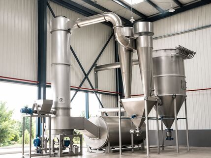
Pneumatic Flash Drying, frequently categorized as high-velocity dispersion drying, is an ultra-fast, continuous thermal processing method engineered specifically to handle damp powders, surface-moist solids, dewatered filter cakes, and thixotropic inorganic pastes.
Regarding mechanical architecture and operational flow, a pneumatic flash drying system consists of a heavy-duty feeding unit, a high-shear mechanical disintegrator, a tall vertical drying duct (or flash tube), a high-efficiency primary cyclone, and a secondary fabric bag filter assembly.
Initially, wet feed material—such as high-moisture filter cake discharged directly from a membrane filter press—is loaded into a feed hopper equipped with variable-speed twin-screw feeders. The feeder continuously transfers the cohesive cake into a high-shear mechanical disintegrator or cage mill positioned directly at the bottom base of the vertical drying duct. At this critical point, rotating high-speed impellers break the sticky, dense filter cake into fine, discrete micro-fragments directly in the presence of an incoming hot air stream.
Simultaneously, a high-pressure supply fan forces heated process air into the base of the duct at extreme velocities, typically ranging from 15 meters per second to 32 meters per second. As the mechanically fragmented wet particles enter this high-velocity, turbulent gas stream, they instantly become entrained and are swept upward through the vertical flash pipe.
Because the particle size is significantly reduced by the disintegrator, the available surface area for convective heat transfer expands exponentially. Furthermore, due to the high relative velocity difference between the fast-moving hot gas stream and the heavier solid particles, extraordinary heat and mass transfer rates are achieved. As a direct result, moisture on and near the particle surface vaporizes almost instantaneously during the upward pneumatic journey, which lasts merely 1 to 4 seconds.
Furthermore, a classifying section or classifier elbow installed at the top of the vertical duct ensures that any larger, under-dried particles or heavy agglomerates lose velocity and drop back down into the disintegration zone for further size reduction and re-drying. Conversely, fully dried, lightweight fine particles pass through the top elbow and enter high-efficiency cyclone collectors and pulse-jet bag houses for complete product recovery.
Operational Parameters and Thermal Data
- Inlet Gas Temperature Range: 200°C to 650°C.
- Outlet Exhaust Temperature Range: 85°C to 135°C.
- Pneumatic Conveying Gas Velocity: 15 m/s to 32 m/s.
- Inlet Feed Moisture Content: 35% to 85% (ideal for heavy filter cakes).
- Final Product Residual Moisture: 1.0% to 4.0% by weight.
- Particle Residence Time: 1 second to 4 seconds (flash thermal exposure).
- Thermal Efficiency: 65% to 82% (exceptionally high due to intimate direct particle-gas contact).
- Evaporation Capacity: 100 kg/h up to 20,000 kg/h of water removal per unit column.
Ideal Product Application: Precipitated Silica Filter Cakes
Pneumatic Flash Dryers equipped with active mechanical disintegrators clearly represent the definitive industry standard for drying Precipitated Silica filter press cakes and dewatered synthetic silicate precipitates.
Detailed Process Breakdown for Precipitated Silica
- High-Moisture Filter Cake Feed: Initially, precipitated silica filter cake containing 75% to 82% water content is delivered directly from membrane filter presses into the flash dryer feed hopper.
- Active High-Shear Disintegration: Next, as the cohesive, thixotropic cake enters the base of the drying tube, high-speed rotating impellers smash the cake into micro-particles, preventing large lumps from forming.
- High-Velocity Pneumatic Flash Drying: Subsequently, hot air entering at 450°C to 550°C sweeps the micro-fragments upward through the drying pipe at velocities of 22 meters per second. Surface water vaporizes in 1 to 3 seconds.
- Pore Network Structural Retention: Because the water flashes off so rapidly under intense pneumatic convection, capillary forces are minimized, thereby preventing the collapse of the delicate silica framework.
- High-Performance Surface Area: Consequently, the dry silica powder emerges with its micro-porous structure completely intact, yielding specific surface areas ranging from 150 to 250 square meters per gram and oil absorption values exceeding 200 milliliters per 100 grams.
3. Vibratory Fluidised Bed Drying Systems (VFBD)
Working Principle and Process Mechanics
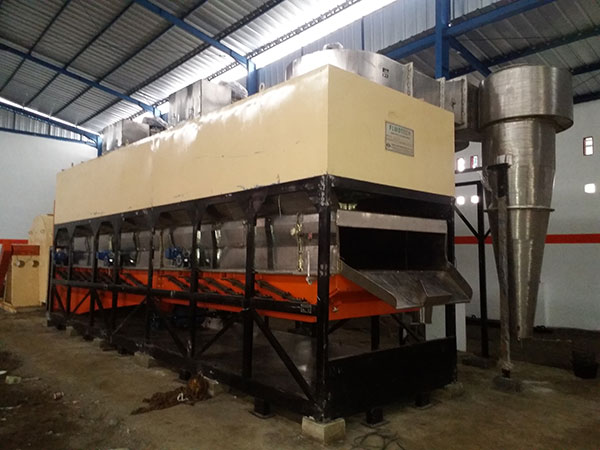
In sharp contrast to high-velocity flash dryers, Vibratory Fluidised Bed Drying combines mechanical vibration physics with low-velocity upward gas fluidization to offer a gentle, highly controllable thermal environment for drying crystalline, granular, pelleted, or fragile inorganic products.
In terms of mechanical construction, a Vibratory Fluidised Bed Dryer consists of an elongated, horizontal processing chamber equipped with a specialized perforated bed plate. The entire dryer body is mounted on heavy-duty isolation springs and is driven by dual out-of-balance electric vibratory motors. These motors apply precise, directional sinusoidal vibrations to the dryer structure at defined frequencies and amplitudes.
Initially, moist granular or crystalline material is introduced continuously through an inlet chute onto the starting section of the perforated deck. The directional mechanical vibration imparts a forward bouncing movement to the solids, causing the material bed to travel along the deck at a highly uniform, predictable depth and speed.
Simultaneously, conditioned hot process air is forced upward from a lower pressure plenum through the precision perforations in the bed plate. This upward air stream flows directly through the moving material bed at low velocities, typically between 0.5 meters per second and 2.5 meters per second.
Crucially, the combination of mechanical vibration and upward airflow significantly reduces the minimum gas velocity required to fluidize the solid particles compared to static fluid beds. As a direct result, the individual particles become gently suspended in mid-air, behaving as a churning, bubbling fluid stream. This state provides maximum surface contact between every single particle and the surrounding hot gas, enabling extremely rapid heat transfer while completely eliminating hot-spots or localized overheating.
Furthermore, because the forward motion of the bed is controlled by mechanical vibration rather than high air velocities, the particles move in a true plug-flow pattern. This guarantees that every particle resides inside the dryer for an identical duration. Additionally, Vibratory Fluidised Bed Dryers can be constructed with multiple, independently controlled temperature zones along the deck length. For example, the initial zone can apply higher heat for rapid surface moisture removal, the intermediate zone can apply lower heat for controlled internal moisture diffusion, and the final discharge zone can blow chilled, dehumidified air to cool the product prior to bulk packaging.
Operational Parameters and Thermal Data
- Inlet Air Temperature Range: 80°C to 280°C.
- Outlet Air Temperature Range: 50°C to 90°C.
- Upward Fluidization Air Velocity: 0.5 m/s to 2.5 m/s (low-velocity airflow).
- Vibration Frequency Range: 10 Hz to 25 Hz (750 RPM to 1500 RPM).
- Vibration Stroke Amplitude: 2.0 mm to 6.0 mm.
- Inlet Material Moisture Content: 5% to 25% free water.
- Final Product Residual Moisture: Down to less than 0.1% by weight.
- Bed Residence Time: 5 minutes to 45 minutes (fully adjustable via vibration drive settings).
- Thermal Efficiency: 70% to 88% (highly efficient, especially with exhaust air recirculation loops).
Ideal Product Application: Granulated Water-Treatment Salts and Synthetic Zeolites
Vibratory Fluidised Bed Dryers excel at drying crystalline, pelleted, extruded, or granular water-treatment materials, including crystalline aluminum sulfate, granular polyferric sulfate, extruded molecular sieve beads, and synthetic zeolite granules.
Detailed Process Breakdown for Granulated Coagulants and Zeolites
- Granular Feed Input: Initially, pre-granulated or crystallized material containing 10% to 18% surface moisture enters the vibratory deck at a controlled feed rate.
- Assisted Bed Fluidization: Next, directional mechanical vibration distributes the particles evenly across the deck width, maintaining a uniform bed depth of 75 mm to 125 mm.
- Multi-Zone Thermal Processing: Subsequently, air heated to 140°C passes through the perforated plate in Zone 1 to remove surface water, while Zone 2 applies air at 100°C to extract internal pore moisture safely.
- Integrated Product Cooling: In Zone 3, cool air at 20°C lowers the granule temperature to below 35°C, effectively preventing atmospheric moisture re-absorption during downstream bag filling operations.
- Zero Attrition and Dust Control: Because fluidization gas velocities are kept low, fragile granules suffer zero particle breakdown, preserving precise particle size distributions and eliminating fine dust generation.
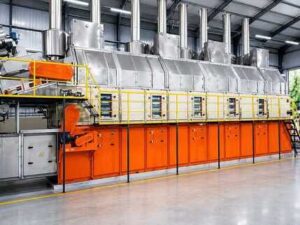
4. Combination Drying Systems (Staged Tray + Fluidised Bed Systems)
Working Principle and Process Mechanics
Combination Drying Systems utilize a multi-staged, multi-phase thermal processing strategy designed to solve complex industrial drying challenges that single-stage dryers cannot address efficiently. Specifically, these systems combine an initial gentle, low-velocity tray or moving-belt tunnel zone with a secondary, high-efficiency fluidised bed finishing zone.
In chemical processing, certain inorganic pastes, extruded hydrogels, sticky coagulant precipitates, and synthetic clay minerals exhibit extreme sensitivity during initial moisture removal. If these raw materials encounter high hot air temperatures or high velocity gas streams while their moisture content is high, they undergo a damaging phenomenon known as case-hardening. Case-hardening occurs when the outer surface of a moist particle dries too quickly, shrinking and forming a dense, non-porous outer crust. This crust traps water deep inside the core of the particle. If heating continues, trapped water creates internal vapor pressure, causing the particle to rupture, crack, or collapse structurally.
To solve this issue, Combination Dryers divide the process into two distinct thermal stages:
Stage 1: Controlled Dehydration Zone (Tray / Belt Mechanism)
Initially, the sticky paste, extruded gel, or cohesive filter cake enters Stage 1, where it is distributed onto multi-pass moving perforated trays or continuous woven wire belts inside an insulated tunnel housing. Here, low-velocity heated air (flowing at 60°C to 120°C) passes gently over and through the product layer.
This gentle primary zone slowly removes free surface moisture and unbound water without inducing high mechanical shear or surface stress. Consequently, the material dries gradually from the outside in, losing its surface stickiness and consolidating into firm, non-cohesive discrete fragments without developing an impermeable outer crust. Bulk moisture is systematically reduced from initial levels of 40%–70% down to roughly 20%–25%.
Stage 2: Integrated Fluidised Bed Finishing Zone
Once the material becomes non-sticky and structurally stable, it drops continuously from the end of the Stage 1 belt directly into Stage 2: an integrated fluidised bed section.
In this secondary zone, higher air velocities (0.8 m/s to 2.2 m/s) and elevated temperatures (100°C to 200°C) fluidize the partially dried particles. Because the product is now non-sticky and permeable, the fluidized state promotes rapid convective mass transfer, stripping deep capillary moisture from internal pores down to extremely low final levels (below 0.1% to 0.5%).
Furthermore, exhaust heat leaving the secondary fluidised bed zone (which remains hot and relatively dry) is cascaded back into the primary tray zone. This heat integration significantly boosts total plant energy efficiency.
Operational Parameters and Thermal Data
- (Tray / Belt Zone) Temperature Range: 60°C to 120°C (low thermal stress zone).
- (Fluid Bed Zone) Temperature Range: 100°C to 200°C (high mass transfer zone).
- 1 Air Velocity: 0.2 m/s to 0.8 m/s (gentle, non-disruptive airflow).
- 2 Air Velocity: 0.8 m/s to 2.2 m/s (active fluidization velocity).
- Inlet Material Moisture Capability: 30% to 70% water content.
- Final Product Residual Moisture: Down to less than 0.1% by weight.
- Total Process Residence Time: 30 minutes to 180 minutes (staged, extended residence time).
- Thermal Efficiency: 75% to 90% (achieved via cascaded exhaust air thermal integration).
Ideal Product Application: Hydrogel Coagulants, Active Alumina, and Specialty Additives
Combination Dryers offer an ideal solution for sensitive hydrogel-based coagulants, active alumina spheres, specialty inorganic catalysts, and modified clay absorbents that are highly prone to cracking or case-hardening.
Detailed Process Breakdown for Hydrogel Additives and Alumina
- Extruded Hydrogel Feed Entry: Initially, wet extruded inorganic gel beads or alumina hydrogel spheres containing 65% water content are fed onto the Stage 1 moving tray deck.
- Gentle Surface Drying: Next, low-velocity air at 80°C removes free surface water over a 45-minute residence period, allowing the gel beads to firm up without shrinking unevenly or cracking.
- Transition to Stage 2: Subsequently, the pre-dried, firm beads discharge smoothly into the integrated fluidised bed section.
- Deep Pore Moisture Extraction: In Stage 2, hot air at 150°C fluidizes the beads, rapidly driving out deep internal capillary water down to a final moisture level of 0.1%.
- Maximum Crush Strength and Porosity: Ultimately, the final dry spheres retain their mechanical crush strength, uniform spherical shape, and maximum internal surface porosity.
5. Industrial Rotary Drum Drying Systems
Working Principle and Process Mechanics
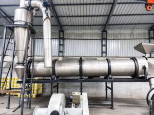
Industrial Rotary Drum Drying represents a continuous thermal processing method engineered for processing high-tonnage bulk materials, raw mineral ores, heavy inorganic chemical salts, and dense industrial wastewater sludges.
Regarding mechanical design, a Rotary Drum Dryer consists of a massive, heavy-duty cylindrical steel shell mounted at a slight downward inclination angle, typically between 2% and 5% grade slope. The drum shell rests on heavy, precision-machined forged steel trunnion rollers and thrust bearings, and is rotated slowly along its longitudinal axis at speeds ranging from 1.5 RPM to 8 RPM by an electric motor connected to a girth gear and pinion drive assembly.
Initially, wet bulk chemical feed is introduced into the elevated front end of the rotating drum using a heavy-duty water-cooled feed chute or a high-torque ribbon screw feeder. Simultaneously, hot process gas—generated by direct-fired gas or oil burners, or indirect steam tube heat exchangers—enters the drum shell. The gas flow can be arranged in either a co-current configuration (flowing in the same direction as the solid material) or a counter-current configuration (flowing opposite to the solid material path).
Inside the rotating drum, a complex array of internal metal flight lifters is welded to the inner shell wall. As the drum rotates, these specialized lifters scoop up the wet material from the bottom bed and carry it upward toward the top of the rotation cycle. When the flights reach the upper arc, they drop the material, creating a dense curtain of falling solids across the entire cross-sectional area of the cylinder.
As hot gas passes through this continuous cascading curtain of solids, rapid heat transfer occurs via direct convection and conduction from the heated drum walls and flights. Owing to the downward slope of the drum combined with mechanical rotation, the material slowly cascades forward toward the lower discharge end. Finally, fully dried bulk material exits through a discharge hood, while moisture-laden exhaust air is drawn out by an induced draft fan and passed through cyclonic scrubbers or venturi washers for dust control.
Operational Parameters and Thermal Data
- Inlet Gas Temperature Range: 250°C to 800°C (direct-fired) or 150°C to 350°C (indirect steam tube).
- Outlet Exhaust Gas Temperature Range: 90°C to 150°C.
- Drum Shell Rotation Speed: 1.5 RPM to 8.0 RPM.
- Drum Shell Inclination Angle: 2% to 5% grade slope.
- Inlet Feed Moisture Capability: 10% to 50% bulk moisture.
- Final Product Residual Moisture: 0.5% to 3.0% by weight.
- Residence Time: 10 minutes to 60 minutes (extended bulk residence time).
- Production Throughput: 1 ton per hour up to 50 tons per hour per single drum shell.
- Thermal Efficiency: 60% to 78%.
Ideal Product Application: Ferrous Sulfate, Bulk Alum, and Calcium Carbonate Sludges
Rotary Drum Dryers provide unmatched mechanical durability for heavy-duty chemical manufacturing operations, such as converting ferrous sulfate heptahydrate into monohydrate, drying bulk aluminum sulfate, and processing heavy precipitated calcium carbonate sludges.
Detailed Process Breakdown for Ferrous Sulfate Conversion
- Bulk Wet Crystal Feed: Initially, moist ferrous sulfate heptahydrate crystals containing surface water and 45% bound hydration water enter the upper end of the inclined drum.
- Cascading Lifter Mechanics: Next, internal flight lifters continuously lift the heavy crystals and shower them through the hot gas stream.
- Controlled Phase Dehydration: Direct contact with hot gases entering at 450°C drives off surface moisture and precisely strips six molecules of hydration water, converting the compound into stable ferrous sulfate monohydrate.
- Thermal Temperature Control: The extended residence time inside the drum allows operators to maintain bed temperatures precisely at target levels, preventing unwanted melting or sticky phase transitions.
- Continuous Heavy-Duty Output: Ultimately, the system delivers high-tonnage output continuously under demanding, abrasive industrial operating conditions.
Detailed Technology Comparison for Chemical Process Engineers
To assist plant design engineers, technical consultants, and operations managers in evaluating thermal drying equipment, the following comparative matrix provides a side-by-side technical overview across all five dryer types:
| Operating Parameter / Feature | Industrial Spray Dryer | Pneumatic Flash Dryer | Vibratory Fluidised Bed Dryer | Combination Dryer (Staged System) | Industrial Rotary Drum Dryer |
| Primary Feed Physical Form | Pumpable liquids, solutions, slurries | Dewatered filter cakes, pastes, damp powders | Granules, pellets, crystals, extrusions | Extrusions, gels, sticky pastes | Bulk aggregates, heavy cakes, sludges |
| Typical Inlet Temperature Range | 180°C to 550°C | 200°C to 650°C | 80°C to 280°C | Stage 1: 60–120°C; Stage 2: 100–200°C | 250°C to 800°C |
| Process Residence Time | 5 to 30 Seconds | 1 to 4 Seconds | 5 to 45 Minutes | 30 to 180 Minutes | 10 to 60 Minutes |
| Evaporation Rate Capacity | High (Up to 25,000 kg/h) | High (Up to 20,000 kg/h) | Moderate (Up to 8,000 kg/h) | Moderate (Up to 5,000 kg/h) | Extreme (Up to 30,000 kg/h) |
| Final Residual Moisture Level | 0.5% to 3.0% | 1.0% to 4.0% | Down to < 0.1% | Down to < 0.1% | 0.5% to 3.0% |
| Particle Size Control Mechanism | Atomizer type, speed, & nozzle pressure | Disintegrator speed & velocity classifier | Feed screen pre-sizing & low velocity | Extruder die size & tray loading | Internal flight arrangement & slope |
| Risk of Case-Hardening | Zero (Instant flash drying) | Very Low (Micro-fragmentation) | Low (Multi-zone control) | Zero (Designed specifically to eliminate) | Low (Continuous surface renewal) |
| Material Construction Options | SS316L, Hastelloy C-276, Titanium | SS316L, Rubber-lined, Alloy 20 | SS304, SS316L, Titanium Grade 2 | SS304, SS316L | Carbon Steel, Heavy SS316 Shell |
Targeted Product-Dryer Pairing Guide
To simplify equipment selection, the following table summarizes the recommended dryer pairings for key water-treatment chemicals and specialty inorganic additives:
| Target Material Category | Recommended Dryer Technology | Key Engineering Reason | Primary Operational Benefit |
| Polyaluminum Chloride (PAC) | Industrial Spray Dryer | Instant liquid-to-powder flash evaporation | Preserves basicity levels and ensures 100% solubility |
| Precipitated Silica Filter Cake | Pneumatic Flash Dryer | High-shear disintegration with rapid lift | Maintains micro-porosity and high specific surface area |
| Aluminum Sulfate Granules | Vibratory Fluidised Bed Dryer | Low-velocity vibration-assisted fluidization | Prevents particle breakdown and eliminates fine dust |
| Ferrous Sulfate / Bulk Alum | Industrial Rotary Drum Dryer | High-capacity cascading mechanical drum | Tolerates abrasive feed and variable input moisture |
| Synthetic Zeolites & Sieve Beads | Vibratory Fluidised Bed Dryer | Multi-zone heating with integrated cooling | Delivers deep drying below 0.1% without particle damage |
| Extruded Hydrogel Coagulants | Combination Dryer (Staged) | Gentle primary tray zone followed by fluid bed | Prevents surface crusting, cracking, and core moisture traps |
| Titanium Dioxide Intermediates | Pneumatic Flash Dryer | High convective heat transfer rates | High energy efficiency with continuous fine powder discharge |
Key Technical Engineering Considerations for Chemical Drying Installations
When planning and designing an industrial thermal drying system for inorganic chemicals and water-treatment compounds, project engineering teams must carefully evaluate several critical auxiliary factors:
1. Metallurgy and Corrosion Resistance
As highlighted earlier, many inorganic water-treatment chemicals—particularly acidic coagulants like ferric chloride, aluminum sulfate, and polyaluminum chloride—become intensely corrosive at elevated temperatures in the presence of vaporized water.
Consequently, standard carbon steel or basic 304-grade stainless steel will experience severe pitting, stress corrosion cracking, and rapid wall thinning. Therefore, wet-zone contact surfaces, drying chambers, ductwork, and cyclone separators should be fabricated from high-grade Stainless Steel 316L, Alloy 20, Hastelloy C-276, or Titanium Grade 2. Furthermore, for non-heated ductwork handling wet exhaust gases, specialized corrosion-proof fluoropolymer coatings (such as PTFE or ETFE) offer robust long-term protection.
2. Fine Dust Collection and Exhaust Air Cleaning
Furthermore, fine inorganic powders—such as precipitated silica, synthetic silicates, and dry coagulant fines—present significant environmental health, safety, and operational dust challenges.
Therefore, drying systems must incorporate multi-stage emission control systems. This typically involves high-efficiency primary cyclones designed to recover 95% to 98% of the bulk product, followed by secondary pulse-jet membrane bag houses fitted with PTFE-coated filter media capable of capturing ultra-fine sub-micron dust particles down to emission concentrations below 10 milligrams per cubic meter. Additionally, when processing acidic exhaust streams, wet scrubbers operating with alkaline scrubbing liquors must be installed downstream to ensure complete compliance with local environmental air quality standards.
3. Thermal Energy Efficiency and Heat Recovery
Above all, thermal energy represents the single largest ongoing operating expense in chemical drying plants.
To maximize operational profitability, modern industrial dryers must incorporate heat recovery technologies. For instance, air-to-air recuperative heat exchangers can be installed on dryer exhaust ducts to capture waste thermal energy from hot exhaust air (typically leaving at 90°C to 130°C) and preheat incoming fresh combustion air. Furthermore, in fluidised bed and rotary drum installations, recirculating up to 50% of clean, unsaturated exhaust gas back into the heater inlet loop can cut overall fuel consumption by 20% to 35%, significantly improving plant profitability.
Conclusion
In conclusion, selecting the optimal thermal drying technology is one of the most critical decisions facing manufacturers of water-treatment chemicals, specialty inorganic additives, and precipitated silica products. As detailed throughout this technical guide, no single drying dynamic can successfully address the diverse physical forms, moisture binding properties, thermal sensitivities, and functional requirements of these chemical compounds.
Whether converting liquid polyaluminum chloride into rapidly soluble powder using an Industrial Spray Dryer, preserving the delicate porous structure of precipitated silica in a high-velocity Pneumatic Flash Dryer, achieving deep residual moisture removal with zero particle breakdown in a Vibratory Fluidised Bed Dryer, handling heavy bulk salts in a heavy-duty Rotary Drum Dryer, or eliminating surface cracking in sensitive hydrogels using a staged Combination Dryer, matching the material characteristics to the correct thermal engineering solution directly drives product quality, operating efficiency, and commercial success.
At GENEX Tech Industries LLP, our thermal engineering team brings decades of technical expertise and manufacturing capabilities to every project. We specialize in designing, manufacturing, and commissioning custom industrial drying installations built specifically for the demanding operating environments of the global chemical and water-treatment industries. From initial material testing and pilot-plant validation to complete turnkey engineering, procurement, and construction, we partner with you to deliver robust, high-performance thermal processing solutions.
Contact Our Thermal Engineering Team
Take the next step in optimizing your chemical drying operations today. Contact our technical team to discuss your process requirements, schedule pilot-plant drying trials, or receive a comprehensive custom proposal tailored to your facility:
-
Head Office Address: 10C, Sir William Jones Sarani (Middleton Row), Park Street, Kolkata – 700071, West Bengal, India
-
Direct Phone / WhatsApp Contact: +91-97489 06968 | +91-93300 77417
-
Official Business Email: mktg@foodtechprojects.com | sales@foodtechprojects.com
-
Official Company Websites: www.foodtechprojects.com | www.gtidryers.com